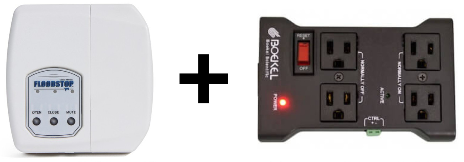
This project utilizes a IoT Relay to power off an appliance when water is detected by the Floodstop system. This project can be very useful to power off a washing machine, water recirculator, or tankless hot water heater if a leak is detected. In particular, appliances that can pump water such as a washing machine have an extra vulnerability for flooding and could potentially continue pumping water even if the water supply has been shut off by the Floodstop valve. For these type of devices, you may want to automatically power them off to ensure any motors or pumps are not contributing to the flooding condition.
Floodstop + IoT Relay Project Objective
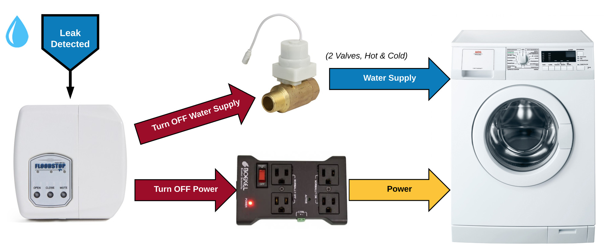
The following diagram illustrates this project's goals.
Shopping List
- Floodstop Protection System (See a complete listing of available Floodstop products)
- IoT Relay
- Low-Voltage DC Power Supply (5-12VDC)
- A length of 2-conductor low-voltage wire (bell wire, alarm wire, speaker wire, etc.) (* length is based on your installation requirements)
| Floodstop FS3/4H-90 |
Floodstop FS3/4NTP |
IoT Relay | DC Power Supply | Low Voltage Wire | Wire Stripper |
|---|---|---|---|---|---|
| Washing Machine 3/4" 90-degree |
Water Heater 3/4" NTP |
12-Amp Max | 12VDC / 1 Amp | 500 ft. 22 gauge/2 conductor |
30-20 AWG |
View all Floodstop models View other supported Power Controllers View other DC Power Supplies
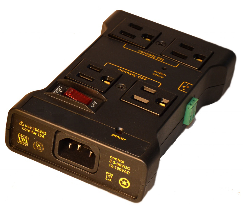
IoT Relay
The IoT Relay is a simple, flexible and extremely cost friendly device for controlling (turning ON and OFF) an appliance using a low-voltage signal circuit. The IoT Relay is manufactured by Digital Loggers, Inc. The IoT Relay can handle appliances (or combined loads if multiple devices are plugged in) up to 12-Amps. Please take care to never overload the circuit with an appliances that draw a combined load of more than 12-amps.
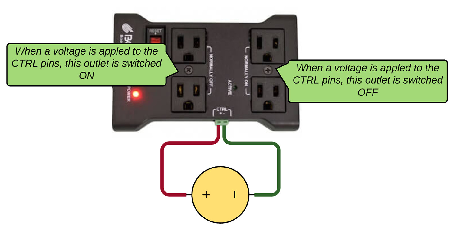
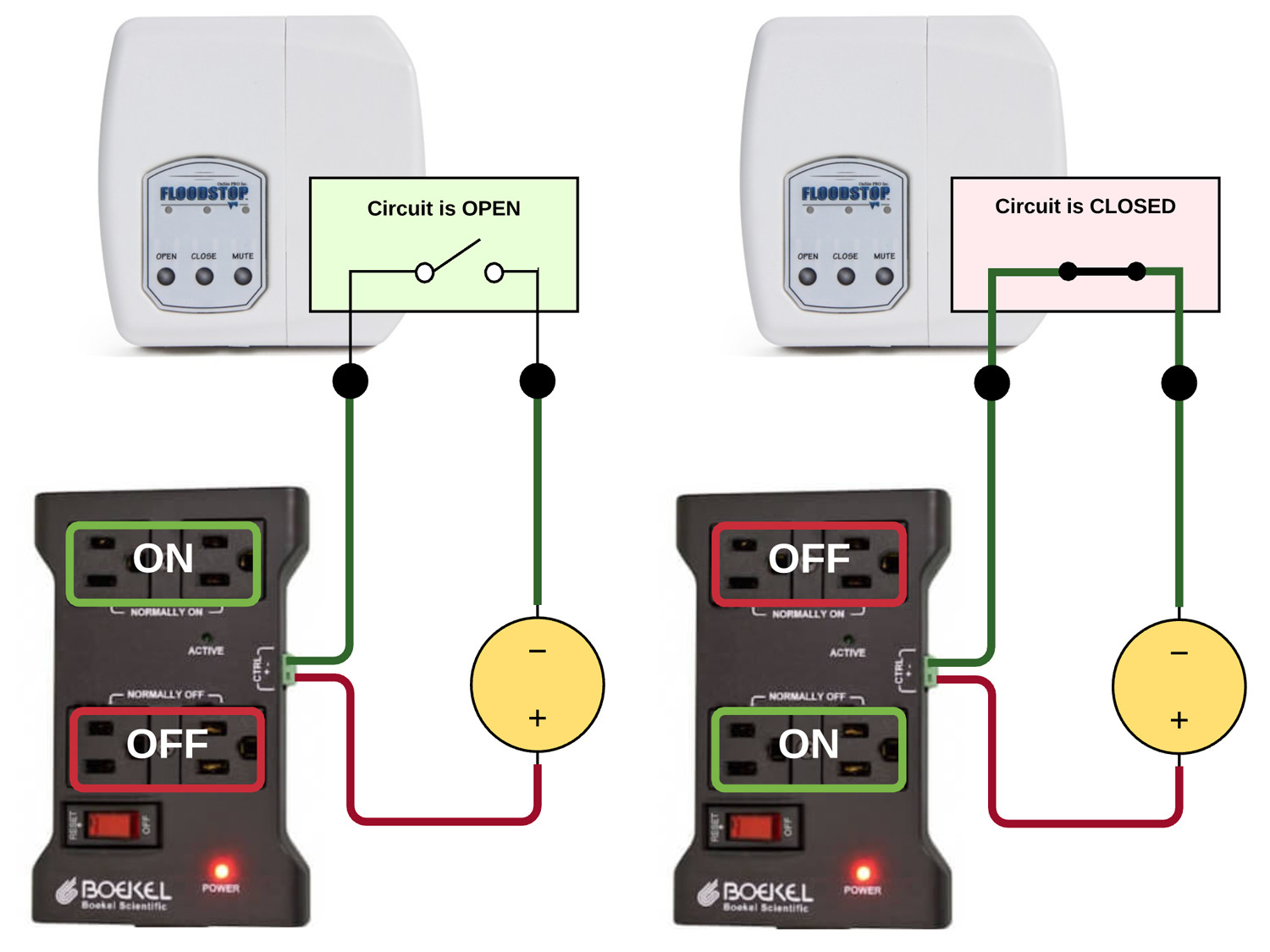
The IoT Relay provides 4 outlets where the left bank of two outlets are normally OFF and the right bank of two outlets are normally ON. When a signal voltage ranging between 3.3-60 VDC or 12-120 VAC is applied to the input connection, the internal relay is activated and the left bank of two outlets are switched ON and the right bank of two outlets are switched OFF. The diagram below illustrates the input logic signal. The IoT relay does not provide a low-voltage source for the input signal so you must provide this separately.
Download Spec Sheet: http://www.digital-loggers.com/IOTSPEC.PDF
Floodstop + IoT Relay Logic
The IoT Relay is easy to integrate with the Floodstop's N.O. (normally-open) dry contact output using a low-voltage power supply to power the signal circuit. The logic diagram below depicts how we will use the low-voltage signal across the Floodstop's dry contact output connection to control the IoT Relay.
Connect Floodstop to the IoT Relay
To control the IoT Relay with the Floodstop you will need a spearate low-voltage power supply. You could tap into the power supply provided with the Floodstop and use it to power both the Floodstop and the signaling circuit or if you prefer you can use a seperate DC power supply to power the signal circuit. You may have an old power supply laying around that you can use for this project or your can purchase one of these. Just make sure the output voltage of the power supply conforms to the signal requirements of 3.3-60 VDC or 12-120VAC (which for the IoT Relay is a very broad range).
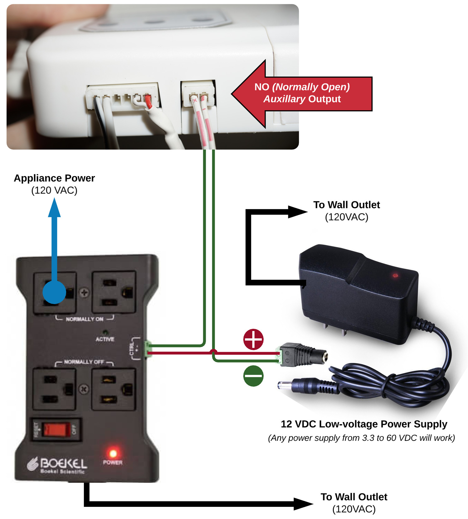
First located the N.O. (normally-open) output on the bottom of the Floodstop controller. This is the port we will be using to interface to the Floodstop.
A short connection wire should have been included in the Floodstop package that includes the necessary plug to connect to the Floodstop's output port. Most likely this connection "pigtail" will be too short for your final installation, so you can extend this connection wire by splicing on the end of a 2-conductor low-voltage wire that meets your project's length requirements.
Next, you will need to attach the positive (+) conductor from the low-voltage power supply to the positive (+) input pin on the IoT Relay (depicted by the red line in the wiring diagram below). Next, the negative (-) conductor from the power supply should be attached to one of the pins on the Floodstop's output port (depicted by the green line in the wiring diagram below). And, finally, a connection must be made from the second pin on the Floodstop output port to the negative (-) signal input pin on the Iot Relay (depicted by the green line in the wiring diagram below).
That's it, you are ready to test and install this project! The IoT Relay should now power off the high-voltage circuit the appliance is plugged into anytime the Floodstop senses a water leak! Please note that once the sensor is tripped, it does not automatically restore power when the Floodstop stops sensing moisture. To restore power to the appliance, the Floodstop sensor must be completely dry and you must press the OPEN button on the Floodstop controller. This will both open the water valves and signal the IoT Relay to restore power to the appliance.
Rate This Article: |
Share This Article: |
 Copyright © 2026, Robert Savage (savagehomeautomation.com)

Comments / Discussion: